



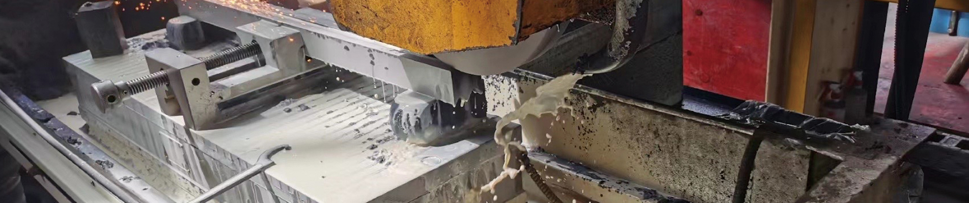

A circular slitter knife can look flawless on a purchasing photograph and still fail on the machine. Its edge may be sharp, its material grade may be correct, and its outside diameter may match the drawing. Yet the finished rolls show fuzzy edges, inconsistent slit width, metal burrs, film stretching or unusually rapid blade wear. In cases like these, the missing specification may be slitter knife runout, face flatness, side-face parallelism or the way the knife is located and clamped on its actual shaft.
These characteristics are easy to confuse because they all describe small geometric deviations. They are not interchangeable. A knife with low radial runout can still wobble sideways. Two faces can be parallel without being truly flat. A perfectly machined bore can rotate eccentrically if an arbor shoulder is damaged. Conversely, a knife that passes inspection on a precision mandrel may appear inaccurate when mounted on a worn production hub.
This guide is for converting engineers, slitter operators, quality inspectors, maintenance teams, OEM designers and purchasing managers who need to identify the cause of a poor cut and specify replacement tooling with evidence rather than vague promises. It explains what to measure, how to interpret a dial-indicator reading, when published micron-level tolerances are relevant, and what a useful inspection report should contain. It also connects technical acceptance criteria to real costs: scrap, blade changes, downtime, regrinding, and rejected customer rolls.
Quick answer: Do not approve a rotary knife only because it has the correct diameter, hardness and sharpness. Define the functional reference axis; separately inspect radial runout, axial or face runout, flatness, parallelism, thickness variation and bore fit; then verify the complete knife–holder–arbor assembly. The acceptable limits depend on cutting method, blade design, substrate, speed and the machine manufacturer's requirements. No single micron figure is a universal tolerance for every slitter knife.
Safety and scope: The measurement methods here concern stationary, isolated equipment and controlled inspection fixtures. Never place a hand, probe or loose indicator near exposed cutting edges on a running production machine. Follow lockout/tagout rules, the original equipment manufacturer's instructions and site-specific blade-handling procedures. A deliberately dished, sprung or relieved knife must be assessed against its intended geometry rather than forced to meet an arbitrary flat-disc requirement.
In This Guide
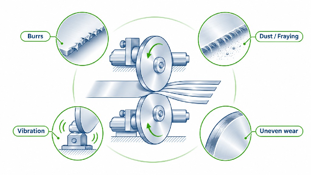
In shear slitting, the upper and lower knives create a moving cutting point. As the material passes through, the edge relationship must remain predictable. A small unwanted sideways movement can disturb contact pressure or clearance. A radial change can alter the local engagement depth. A tilted face can introduce periodic contact, rubbing or heat. These effects may combine with web tension, knife sharpness, material thickness, lower-band condition and holder stiffness.
Consider a line processing six lanes of coated paper. Even if only one cutting position creates excessive dust, the dust may contaminate a downstream process, lower roll appearance quality and force extra cleaning. For thin film, a repeating change in engagement may promote tails, edge stretch or flutter. In metal coil slitting, unstable gap or eccentric tooling can contribute to inconsistent burr geometry, though material properties and clearance remain major variables. Therefore, a quality investigation must look at the entire cutting system, not blame the steel grade automatically.
The economic consequence is often larger than the purchase price of a blade. An inexpensive tool that requires repeated alignment can be more costly than a correctly specified one. A premium carbide knife is also poor value if machine runout causes repeated edge chipping. GUANG CHUAN's circular slitter knife selection guide explains the broader selection decisions; this article concentrates on the geometry and verification that make a selected knife work consistently.
A useful way to diagnose a slitter is to separate four layers: individual knife geometry, mounting interface, rotating machine geometry, and process setup. A certificate of conformance for the blade can address the first layer. It does not certify the other three. This distinction is particularly important when a buyer receives technically acceptable knives but the installed assembly still exhibits substantial total indicated runout.
| Layer | Typical factors | How to evaluate it | Who can correct it |
|---|---|---|---|
| Finished knife | OD, bore, thickness, faces, edge profile, heat-treatment distortion | Bench inspection referenced to the agreed datums | Knife manufacturer or regrinding provider |
| Mounting interface | Burrs, contamination, flange distortion, keyway interference, clamp loading | Clean, inspect and remount; check shoulder and flange | Maintenance and tooling team |
| Machine and holder | Shaft eccentricity, bearing play, hub-face error, holder deflection | Indicator checks at several locations; repeat with reference tool | Machine maintenance or OEM |
| Process setup | Overlap, side force, lateral clearance, cant angle, tension, speed | Controlled trials and quality observations | Process engineer and operator |
A technical quotation should use dimensions and measurement definitions instead of labels such as “super precision.” The following terms often occur together on rotary knife drawings, but each describes a different characteristic. In drawings made under the ISO system, ISO 1101:2017 establishes the geometrical tolerancing language for characteristics including form, orientation and runout. In real contracts, the exact datum scheme and applicable drawing standard still need to be agreed.
| Term | Plain-language meaning | Typical reference or setup | Why it matters |
|---|---|---|---|
| Radial circular runout | Variation measured outward from the rotation axis during one revolution | Functional bore or shaft-derived datum axis | Changes effective cutting radius or engagement |
| Axial or face runout | Sideways indicator variation on a rotating face | Functional axis plus a specified face radius | Can change lateral knife relationship and contact |
| Flatness | Departure of one surface from an ideal plane | Form characteristic, normally no datum for the face itself | Affects seating, contact and stress distribution |
| Parallelism | Orientation of one surface relative to a specified datum plane | Reference face designated as datum | Controls face-to-face alignment, not both faces' absolute flatness |
| Concentricity / coaxial relationship | How centers or axes are aligned | Agreed bore axis and outer feature | Affects whether the outer cutting circle follows the mount |
| Thickness variation | Maximum minus minimum face-to-face thickness at specified points | Defined sampling positions and edge exclusions | Affects stacked width, spacer fit and axial geometry |
Important terminology: Shop-floor language often uses “concentricity” loosely to mean “the bore and OD run true.” Modern GD&T distinguishes different geometric controls, and measuring OD runout is not the same operation as proving a formal concentricity requirement. If function is the issue, a well-defined radial runout test relative to the functional bore may be more practical than an ambiguous “concentricity 0.01” note. Likewise, “TIR” or “FIM” needs a stated probe location, datum, fixture and evaluation method.
The cutting edge is a local feature, while runout is a dynamic relationship. Even a correctly sharpened bevel encounters changing conditions if the knife moves. On a periodic disturbance, one sector of the blade may rub more than the opposite sector. Another sector may cut less aggressively. An operator may attempt to compensate by adding side force, overlap or holder pressure. That sometimes masks the symptom temporarily, while increasing heat and wear elsewhere.
GUANG CHUAN's clearance, overlap and side-force setup guide explains why these adjustments must be considered together. Precision is valuable because it helps the line maintain an acceptable cut with the correct, rather than excessive, engagement and force.
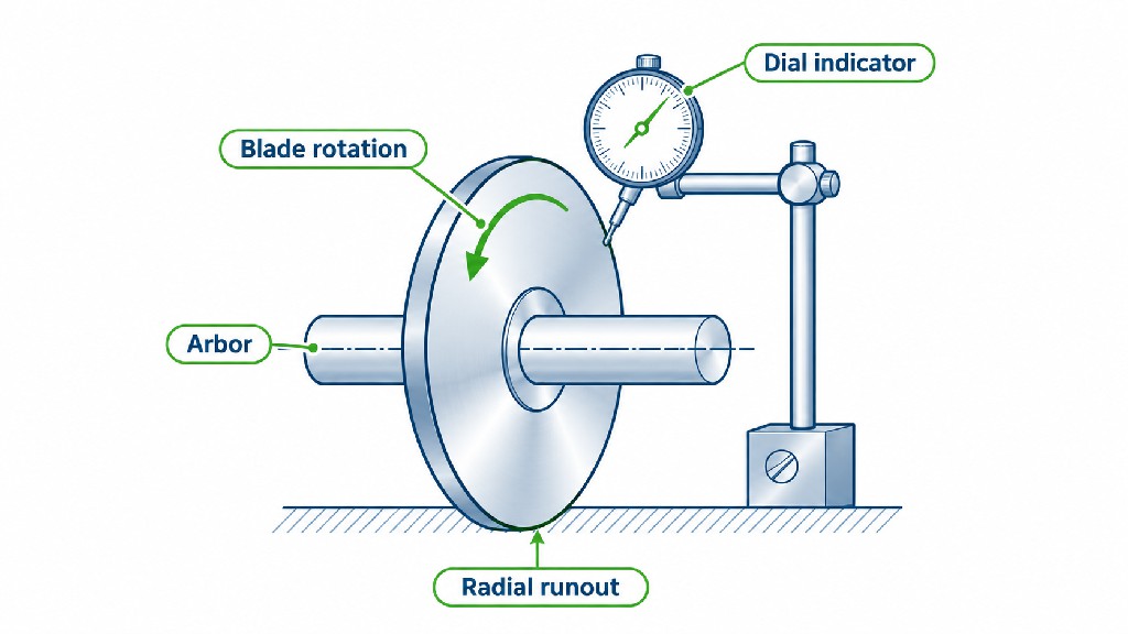
Slitter knife runout is the observed variation of a surface as the tool rotates about an established datum axis. There are two important practical forms. Radial runout describes changes measured normal to the circumference. Axial runout describes variations measured on a face along the shaft axis, typically at a fixed radius. Both are expressed as a total indicator range over the defined test, commonly in millimeters or micrometers.
The measuring location matters. Radial runout measured on the OD is not automatically equivalent to radial runout measured on the sharpened tip if the edge has a separate geometry. Axial runout near the inner bore can be smaller than it is near the outer edge when a face is tilted. An unspecified report stating “runout: 0.01 mm” does not tell a purchaser which movement was measured or whether that result predicts cutting performance.
KEYENCE's guide to circular and total runout distinguishes local circular runout from full-surface total runout and emphasizes a datum axis. A shop-floor dial indicator commonly reports the range of values at one probe position; a complete GD&T verification depends on the feature, tolerance specification and inspection strategy.
Imagine a round knife with its geometric OD center offset from the shaft's rotation axis. The radius presented to the material varies as the knife rotates. A dial indicator following the OD reports a high and a low point. For a mathematically perfect circle with a small pure center offset e, ideal radial indicator variation is approximately 2e. Thus, 0.020 mm of pure eccentricity produces roughly 0.040 mm of radial indicator variation. Real knives can also have roundness error and vibration, so the observed TIR is not a unique measurement of center offset.
Radial runout can disturb overlap or engagement in a way that becomes increasingly visible on sensitive products. However, seeing high radial TIR does not by itself prove that the knife blank was made incorrectly. A poorly fitting bore, debris beneath a locating shoulder, or an eccentric arbor can create the same reading. The first diagnostic question should be: “Relative to which axis was this result measured?”
Axial runout is typically checked by placing an indicator perpendicular to a blade face at a stated radial distance from the center, then turning the blade on its actual datum. If that face is tilted relative to the axis, its apparent axial position changes around the revolution. At a larger measuring radius, the same angular tilt produces a larger variation. A report that omits inspection radius is therefore incomplete when assessing face wobble.
A blade may also be dished by design. A controlled dish is not automatically a defect; it can be important to the way some top shear knives load their mating bands. The relevant question is whether the finished shape, its support and the installed movement match the specified design. An inspector who puts a deliberately sprung knife on a surface plate and expects every point to touch can reject a functioning part for the wrong reason.
In its Slitter Management technical paper, Valmet discusses both radial and axial runout in paper-winder slitting. It provides hub-related guidance of 0.002 inch or less axial runout and 0.004 inch or less radial runout, approximately 0.0508 mm and 0.1016 mm respectively. These are published recommendations for the relevant hub/equipment context, not universal manufacturing limits for every bare slitter blade or precision metal-coil tooling set. The paper also recommends cleaning mounting surfaces and investigating the blade and equipment if excessive runout remains.
| Published Valmet hub guidance | Original value | Metric equivalent | Interpretation |
|---|---|---|---|
| Axial hub runout | 0.002 in maximum | 0.0508 mm = 50.8 µm | Equipment-specific maintenance reference |
| Radial hub runout | 0.004 in maximum | 0.1016 mm = 101.6 µm | Equipment-specific maintenance reference |
The fact that an industrial winder reference uses hundredths of a millimeter while some blade manufacturers market micron-level face accuracy is not contradictory. They describe different objects, methods and operating conditions. It would be a procurement error to apply a paper-winder hub allowance as the acceptance limit for a finely ground bare knife, just as it would be unwise to apply a bare-knife face tolerance to a whole production machine without engineering justification.
The center bore is more than a dimension printed next to the outside diameter. It is often the primary locating feature that defines how a slitter knife sits on a hub, mandrel or arbor. Bore size alone does not guarantee a stable axis. Bore shape, finish, permissible fit, mating shaft condition and clamping arrangement all influence whether the knife can repeat its position after installation.
A knife can have an accurate OD relative to its bore but rotate eccentrically if there is enough clearance for it to settle off-center. A clamp or fastener does not necessarily self-center the blade. A keyway may transmit torque but should not be assumed to provide precise radial location. A shoulder can locate a face only when it is clean, geometrically suitable and able to resist mounting loads. If a tool has multiple bolt holes, their functional role must be distinguished from the actual centering feature.
For purchasing, require the drawing to identify datum A as the bore axis or another functional feature where appropriate. Specify OD runout relative to that datum and define the bore diameter, form and permitted fit. A radial runout callout without a datum may be impossible for different parties to reproduce consistently. If the knife uses a special taper, pilot diameter or integral hub, its actual locating geometry should become the datum rather than automatically using the largest visible hole.
When the problem is intermittent, mark the highest runout location on both the blade and arbor after a careful stationary measurement. Remove the blade, clean and inspect the interface, rotate its angular mounting position if the design safely permits, and measure again using the same indicator and reference. If the high point follows the blade, suspect the blade's geometry or bore relationship. If it remains aligned with the arbor, inspect shaft, shoulder, bearing and fixture. If it changes unpredictably, examine seating, debris, clamp sequence or repeatability. This is a diagnostic comparison, not a substitute for formal inspection.
Do not attempt this experiment with a keyed, pinned or directionally oriented assembly in a way that violates the original design. Many slitter systems must maintain a specific edge direction or defined position relative to other components.
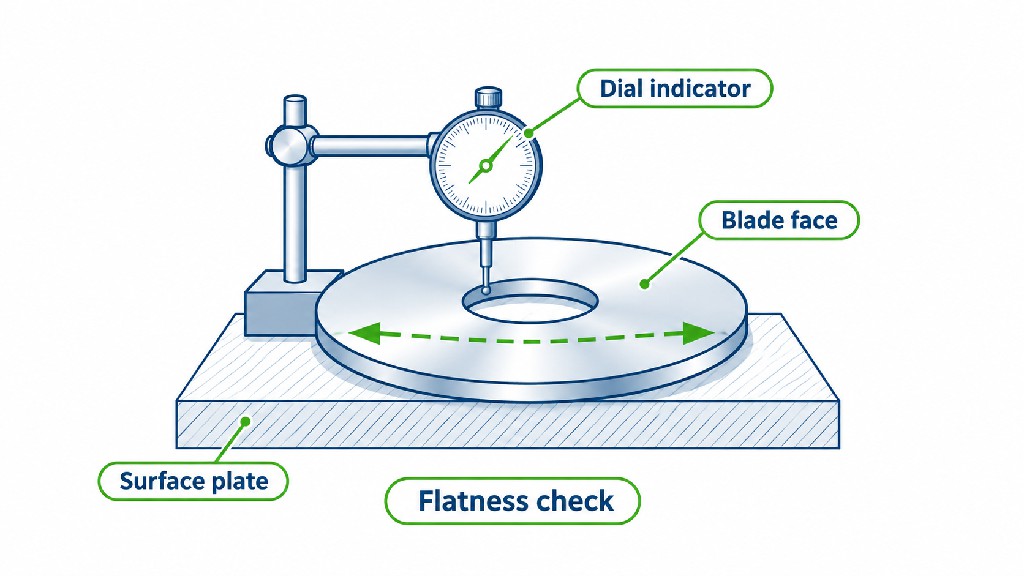
Slitter knife flatness describes the form of a single nominally planar surface. In conventional geometrical tolerancing, flatness concerns whether the surface fits between two parallel planes separated by the specified tolerance. It does not require a separate datum. A surface may have excellent average roughness while still being bowed, warped or saddle-shaped. Surface finish and flatness are different properties.
The distinction becomes critical when a blade is clamped between collars or installed as one element of a stacked metal-coil slitting set. Local high spots may prevent consistent contact, producing stresses as bolts tighten. Very small chips, dirt or corrosion products on a mounting face may have a large effect near the outer diameter. A distorted knife may behave acceptably in one clamp condition and badly in another.
For large and thin discs, gravity, temperature and support conditions can influence measurement. A knife measured free on three points can show a different shape from one measured under a specified clamp load. Neither result is inherently wrong; they answer different questions. Buyers should ask whether the required flatness applies free-state, in a defined supported condition, or after installation. Knife thickness, material, relief geometry and intended application determine which condition is technically meaningful.
Suppose two opposite faces are equally bowed so that their thickness remains almost constant at each sample location. They may be nearly parallel in a local sense yet neither face is flat. Conversely, a lower face can be flat while the upper face is slightly inclined: that produces a wedge in thickness and a parallelism problem. A high-grade tool can require both characteristics, but the print must state how each is measured and which surfaces are included. In particular, do not measure on bevels, dished reliefs, transition radii or other intentionally nonplanar areas and claim those results describe a nominally flat mounting face.
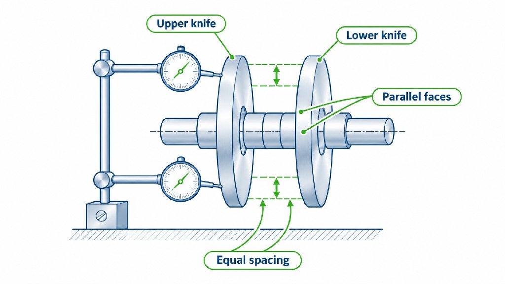
Slitter blade parallelism is an orientation relationship. On a typical flat rotary knife, one major face can serve as a datum plane and the opposite nominally planar face is controlled relative to it. In simplified terms, parallelism prevents the opposite face from leaning too far away from the datum orientation. It is not merely a reading from two random micrometer locations.
Thickness variation is a useful production measurement, but it does not automatically prove an ISO parallelism requirement. A contact micrometer sees differences between the two surfaces, whereas a datum-referenced inspection separates the relationship of the controlled face to the specified datum. The difference may matter when the faces have local form error or when thin tools deflect under probe pressure. Clarify whether a vendor's statement “parallelism 0.005 mm” refers to a formal GD&T evaluation, a face-to-face thickness variation method, or its own inspection procedure.
For a stacked metal-slitting arbor, thickness also affects strip-width setting. A nominally accurate knife can disrupt a spacer stack when the actual thickness deviates from its specified value. Flatness and parallelism contribute to stable contact; spacer width, shoulder geometry and shaft condition control the assembled position. The correct purchase request therefore covers blades and mating spacers, not just cutting edges.
Assume a knife is specified as 5.000 mm thick. Five readings away from the bevel and clamping defects are 5.002, 5.001, 5.003, 5.000 and 5.002 mm. The observed range is 5.003 − 5.000 = 0.003 mm, or 3 µm. That sample supports the statement “observed thickness range at these points: 3 µm.” It does not prove that thickness is everywhere within the required tolerance, nor that the faces meet a formal 3 µm flatness or parallelism limit. The number of samples, inspected annulus, instrument uncertainty and inspection method must be documented.
It is reasonable to ask a supplier for evidence that a precision knife can be produced repeatedly. The difficulty is that public catalogs often publish a few selected figures without specifying the complete evaluation method, diameter, thickness, support condition or process capability distribution. Those figures are useful evidence of what particular manufacturers advertise, but they must not be treated as industry-wide compulsory specifications.
For example, Taiwan-based WEIDER publicly describes slitter knives with thickness tolerance within ±0.002 mm and parallelism within 0.005 mm. TOA DR advertises thickness tolerance within ±0.001 mm and parallelism within 0.005 mm for its slitter knives. KNT Knives lists thickness tolerance ±0.001 mm, flatness 0.002 mm and parallelism 0.002 mm on its high-precision slitter knife page. These are manufacturer-specific claims, not measurements independently audited for this article, and the published pages do not by themselves establish applicability to every knife size or geometry.
| Public manufacturer reference | Published specification | What purchasers may learn | Important limitation |
|---|---|---|---|
| WEIDER Precision Industrial | Thickness ±0.002 mm; parallelism 0.005 mm | Tight face-control figures are marketed for certain slitting tools | Product-specific claim; request drawings and inspection definitions |
| TOA DR / Slitterline | Thickness ±0.001 mm; parallelism 0.005 mm | Thickness and parallelism can carry different values | No reason to assume every diameter or mounting scheme achieves the same values |
| KNT Knives | Thickness ±0.001 mm; flatness 0.002 mm; parallelism 0.002 mm | Flatness and parallelism are explicitly listed as separate metrics | Confirm measuring region, instrument, quantity and acceptance conditions |
| Valmet winder technical paper | Hub axial ≤0.002 in; hub radial ≤0.004 in | Installed equipment requires its own maintenance checks | Values concern its described hub/winder context, not a universal blade manufacturing drawing |
Interpretation rule: Precision numbers are meaningful only when linked to a measurable characteristic, an agreed datum, instrument capability, temperature, inspection state and acceptance method. An RFQ saying “flatness and runout must be very good” gives a factory little useful information. An RFQ saying “face flatness maximum 0.010 mm on the specified annular mounting surface in the free state, evaluated by the agreed method” is much more actionable—although whether 0.010 mm is appropriate still requires engineering validation.
Ultra-tight flatness on a large, thin steel disc may require extra stress relief, grinding, lapping, climate-controlled measurement and careful shipping. If the machine's actual holder repeats at a much coarser level, those extra steps may provide little benefit. Conversely, for foil or narrow precision slitting, an inadequate face tolerance may produce substantial scrap even when the knife is relatively inexpensive. The buyer's target should therefore be the lowest total cost that reliably meets the process, not automatically the smallest available advertised tolerance.
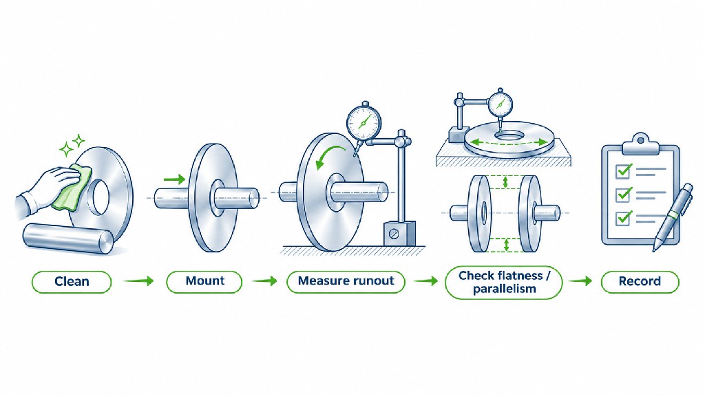
The best inspection method starts with a drawing rather than with a tool catalog. Before selecting a probe, identify the feature, the functional datum, the tolerance zone, the measured surface and the required state of the part. A dial indicator, micrometer, surface plate, dedicated roundness instrument and coordinate-measuring machine can each answer different questions. They are not interchangeable simply because they display a number with three decimal places.
For radial runout, seat the knife on a clean, suitable precision mandrel or a qualified functional arbor. Support the arbor so its rotation is repeatable. Position a suitable dial indicator near the specified outside-diameter measuring band. Rotate the part slowly by hand under a safe inspection procedure and record maximum minus minimum reading for a full revolution. Repeat at the specified location and, where necessary, over multiple revolutions or mounting orientations to understand repeatability.
For axial runout, change the probe direction so it reads the specified side face, normally at a defined radial distance. Keep the contact point away from bevels, holes, markings and edge damage. Do not compare axial readings taken at two different radii as if they were the same measurand. Before interpreting a high result, check the fixture alone and verify the probe is properly aligned, calibrated and not mechanically bottoming out.
For flatness of a defined face, a surface plate with an appropriate comparator setup, a flatness instrument, a CMM or a suitable optical system may be used depending on tolerance, part size and geometry. The method should evaluate enough of the relevant area to detect bows, twist and local high spots. Three-point support, full contact support and clamped inspection can produce different results, particularly for thin discs, so the intended inspection condition must be written down.
Placing a knife on a table and looking for daylight is a quick screening method, not proof of a micron-level flatness value. Similarly, measuring several points against a plate can miss undetected regions. If the mounting face has an annular functional zone, define its inner and outer boundaries and exclude reliefs where they are not intended to seat.
To evaluate geometric parallelism, establish the designated reference face as the datum using an appropriate fixture or data-processing strategy, then inspect the controlled face. For thickness, use calibrated equipment appropriate for the expected range and take readings at positions specified on the control plan. A micrometer with overly high measuring force can elastically deform a thin knife; a poorly chosen anvil can bridge or penetrate surface features. Record the sample positions, not just a single average.
| Instrument or method | Strongest use | Common pitfall | Good reporting practice |
|---|---|---|---|
| Dial test indicator with qualified rotating fixture | Radial and face runout | Fixture runout or loose seating mistaken for knife error | Datum, radius, setup, TIR, repeat result |
| Contact micrometer | Thickness and thickness variation | Contact force, limited point sampling | Locations, measuring force where relevant, min/max |
| Surface plate with comparator | Accessible planar face form | Wrong support or inadequate scan | Support pattern and inspected annulus |
| CMM | Multi-feature geometry and datum relationships | Sampling plan or fixture distorts thin disc | Datum construction, point strategy and uncertainty |
| Roundness / cylindricity system | Detailed OD form and axis-related analysis | Results depend on reference and filtration | Evaluation settings and geometric feature |
| Optical or noncontact measurement | Sensitive surfaces, profiles, edge geometry | Reflectivity, alignment and calibration bias | Method, magnification, uncertainty and traceability |
The following workflow is intended as a supplier or maintenance inspection template. It is not a substitute for the original machine builder's instructions or for a contractual quality control plan. Its purpose is to make two operators more likely to obtain comparable results and locate the same source of error.
For dimensionally critical contracts, use an inspection method compatible with the tolerance and consider measurement uncertainty explicitly. ISO 14253-1:2017 addresses decision rules when measurement results are near specification limits. “The display says 0.005” is not an adequate acceptance argument if the instrument's uncertainty is large relative to the specified tolerance.
Precision inspection should not confuse numerical resolution with true accuracy. A digital indicator that displays increments of 1 µm does not automatically deliver 1 µm uncertainty once the fixture, operator, temperature and part behavior are included. At very small tolerances, the method's capability may become the limiting factor rather than the quality of the finished knife.
Temperature matters because both the disc and the measuring fixture expand or contract. The correct reference temperature for dimensional specification is addressed by ISO 1:2022, which establishes the standard reference temperature concept. It is sensible to record or control temperature during close-tolerance inspection and to avoid comparing one warm part directly against one cool part when demanding micron-level conformity. This is particularly important for larger diameters and dissimilar materials.
Clamp force is another influence. A thin blade may be measurably different before and after the collar is tightened. A distorted flange may cause a locally accurate disc to wobble when installed. A hard but brittle cutting ring may be damaged by excessive pressure or an uneven mating surface. The inspection plan therefore needs to define torque, sequence, fixture contact and whether a special mounting condition is part of the functional requirement.
Finally, acceptance decisions must be realistic about uncertainty. A nominal limit of 0.010 mm and an observed value of 0.009 mm do not necessarily establish a clear pass if the applicable decision rule requires additional allowance for measurement uncertainty. Supplier and customer should agree on how borderline values are handled before parts are shipped. Measurement reports that omit such context often create costly disputes without actually improving cut quality.
An operator who sees the edge oscillate can be tempted to blame the replacement supplier immediately. That conclusion is premature until the mounting and machine have been separated from the tool. A correct investigation begins with controlled measurements on the arbor or hub without the blade, followed by measurements of the blade under an agreed reference setup and then measurements of the installed assembly.
Inspect the shaft's radial runout and the hub shoulder's axial runout at appropriate locations. Check for loose or rough bearings, damaged washers, eccentric collars, scratches and trapped material. A raised burr at the edge of a spacer can tilt a knife even when both components are nominally accurate. Uneven tightening can distort a thin blade. A worn arbor may produce a repeating high spot on many different knives; that observation is stronger evidence of a machine-related cause than a single reading on one new knife.
If a spare reference blade known to be acceptable is available, repeat the test using the same fixture. Compare not just the single largest TIR value but also the high-spot orientation, measurement radius and repeatability. When the assembled result is larger than expected, avoid simply subtracting the independently measured blade and arbor TIR values. Runout includes vector relationships, phase, form and fixture effects; maxima do not generally add as plain scalar errors.
These questions often narrow the investigation faster than ordering a harder steel grade or increasing side load. GUANG CHUAN's top-and-bottom slitter knife geometry guide can help teams distinguish a knife-pair geometry problem from a separate mounting problem.
A visible defect should trigger measurement, not a guess. Different substrate families fail differently: paper creates dust and ragged fibers, film stretches or forms tails, foil wrinkles, and metal strip develops burrs and edge shape defects. Runout is a possible contributor to many of these symptoms, but blade wear, incorrect clearance, material variability and holder pressure can cause similar results.
| Observed symptom | Precision-related hypothesis | Other plausible causes | First useful check |
|---|---|---|---|
| Repeating irregular cut along web length | Periodic radial or axial runout | Tension oscillation, eccentric rollers | Safe offline knife/roller runout comparison |
| Dust on one paper lane | Face wobble or fluctuating contact | Dull edge, excessive side load, poor cant angle | Compare knife station, edge and holder |
| Film tails or uncut fibers | Intermittent engagement | Insufficient overlap, unsuitable bevel or tension | Record cut point and holder setup |
| Unequal wear around circumference | Off-center rotation or face tilt | Material inclusion, contact asymmetry | Mark blade sectors and inspect wear pattern |
| New knife chips rapidly | Mounting wobble, excessive contact | Too brittle a grade, debris, mechanical shock | Runout, clearance and impact history |
| Burrs on metal strip | Unstable knife clearance | Worn edge, wrong gap, material hardness | Edge microscope and installed gap test |
| Width drift on a multi-knife stack | Spacers or blade thickness inconsistent | Thermal growth, tension, wrong setup | Stack dimensional report and arbor alignment |
| Problems follow one holder | Shaft, bearing or holder geometry | Pneumatic fault, mis-sequencing | Compare empty-holder and reference-tool readings |
| Problems follow one blade | Bore/OD relationship or warped face | Bevel damage, grade mismatch | Bench reinspection against drawing |
| Knife rubs even after setup | Axial wobble or dished geometry mismatch | Excessive side force or incorrect mounting | Face runout and bevel orientation |
| Acceptable bench knife, poor installed result | Seating, arbor or clamping error | Incorrect pairing or contact setting | Check bare arbor, remount and repeat |
Record the output defect and the measured mechanical condition together. If cut quality improves after a cleaning or holder repair but the blade has not been replaced, that is useful evidence about the real root cause. Conversely, replacing a knife that is measurably damaged may be justified even if a machine issue contributed to that damage.
For paper, board and other fibrous products, operators often judge quality by dust, edge fuzz, roll appearance and the amount of fiber disturbance. The top knife and lower band should cut consistently with a controlled relationship throughout the rotation. Axial wobble may disturb side contact, while radial variation can change engagement. Uneven wear can also increase dust long before an operator notices obvious chips.
In this application, the best plan combines measurable runout control with maintenance of lower-band sharpness, correct side load and equipment cleanliness. Valmet's technical paper explicitly links blade and band runout to reduced cut quality and service life, while stressing maintenance and correct mounting. For practical edge defects, see GUANG CHUAN's paper slitter knife troubleshooting guide.
Thin, flexible webs are sensitive to tension, geometry, thermal effects and edge quality. A cutting point that periodically changes position can contribute to inconsistent separation, especially where the holder is operating near its stable engagement limit. Yet in razor slitting, a blade does not have the same upper/lower knife relationship as a rotary shear pair; applying shear-knife setup advice to a razor system is an error.
For film, therefore, first identify whether the machine uses rotary shear, razor or score cutting. Then check functional runout requirements appropriate to that mechanism. A very flat rigid blade and a deliberately dished spring-type knife are different design solutions. Neither can be judged correctly without its holder specification. The film slitting blade selection guide offers additional material and edge-profile context.
Thin foil often leaves a narrow process window: a tiny geometric disturbance can be significant compared with the web thickness, but material tension, surface coatings and the exact slitting mechanism still matter. A foil converter should define acceptable edge curl, tears, burr or particles, and should assess whether runout or spindle accuracy is limiting stable cutting. For demanding applications, a qualification trial with the actual film or foil is more persuasive than a vendor brochure claiming “micron precision.”
Dimensional control should include the mating lower ring and spacers. If a knife is reground, its OD and edge geometry may change, which can alter the necessary setup. When a multi-lane line has asymmetric results, inspect knife-by-knife position and holder condition rather than assuming all stations have identical contact.
Metal-coil slitting typically uses robust rotary shear arrangements with a specified knife clearance and stacked tooling. The important precision questions include blade thickness, flatness, parallelism, bore-to-OD geometry, spacer width, shaft accuracy and assembled lateral positioning. An inconsistent stack can alter the relationship between opposing knives. Edge rollover, burnished zone, fracture zone and burr height should be evaluated against material properties and the approved setup—not attributed to runout alone.
A metal-service center may require very tight dimensional control, but there is no responsible way to declare one universal runout limit for all coil thicknesses, grades, knife diameters and machine constructions. Obtain the machine builder's stack tolerances and define the acceptance method with your knife manufacturer. GUANG CHUAN's metal coil slitter knife selection article covers material-specific selection beyond this geometric inspection guide.
Knife accuracy is not permanently fixed at the moment of manufacture. An initially acceptable knife may develop edge chips during use, be damaged in storage, or acquire new geometric errors during maintenance. Regrinding is a controlled machining operation, not merely removal of a visible dull strip. On a rotary knife, grinding can change OD, edge angle, edge radius, dish, face geometry and the relationship of the cutting circle to the locating bore.
Ask the sharpening provider which dimensions are maintained after each service and how many regrinds the design supports. If both faces are ground, assess whether the process preserves the required thickness and parallelism. If only the cutting bevel is ground, verify that the functional cutting diameter, concentric relationship and intended clearance remain valid. For a delicate spring-style top knife, the sharpening procedure must preserve its designed deflection and avoid unintended flattening or excessive thermal loading.
Inspect after regrinding using the same drawing requirements as the incoming inspection, modified only by approved wear or regrind allowances. A knife should not return to the line because its edge looks bright. It should return because the edge is usable, the geometry remains within approved limits and the associated holder is functional. Reference GUANG CHUAN's guide to when circular slitter knives should be resharpened or replaced when defining the maintenance decision.
Handling is equally important. Store knives in a protected carrier that prevents edge-to-edge collision, bending and accidental dropping. Keep precision faces free of abrasive particles and moisture. Do not stack bare blades casually on a shop bench, use their cutting edges as support points, or clamp a slender disc against an uneven surface. Record any impact or suspected bending event and quarantine the part for reinspection instead of relying on visual judgment alone.
A quotation request that contains only “200 mm circular slitter knife, HSS, very accurate” leaves too many functional decisions to chance. Vendors may respond with products that share the same broad description but differ in bore fit, face orientation, edge geometry or achievable tolerance. The right information should appear before a price is negotiated, particularly when the part is intended as an OEM replacement or will be installed in a high-value production line.
| RFQ field | Information to supply | Why it is important |
|---|---|---|
| Machine and cut method | OEM/model; shear, razor, score or metal rotary shear; top/bottom designation | Prevents incompatible knife selection |
| Material being cut | Substrate, thickness range, coating, abrasiveness and strength where relevant | Determines load, edge profile and material |
| Operating conditions | Line speed, knife RPM, temperature, continuous/stop-start duty | Supports design and inspection planning |
| Nominal geometry | OD, bore, thickness, keyway/holes, bevel, relief or dish | Defines part interchangeability |
| Functional datums | Bore axis, support face, pilot or special locating feature | Makes runout inspection reproducible |
| Geometric tolerances | Radial runout, face runout, flatness, parallelism, bore form as needed | Defines acceptance rather than vague quality |
| Thickness control | Nominal thickness, bilateral limits and variation measurement method | Protects spacing and stacked width |
| Material and heat treatment | Grade/standard, hardness range, coating if any | Prevents unsuitable substitutions |
| Inspection definition | Instrument, support/clamp state, probe radius, report frequency, uncertainty rule | Avoids dispute over different measurements |
| Lot assurance | Quantity, traceability, sampling or 100% critical-characteristic inspection | Matches production and risk needs |
| Trial acceptance | Edge defects, scrap criteria, changeover repeatability, service interval | Connects dimensions to production result |
| Logistics | Edge protection, preservation, identification and packaging | Protects precision before installation |
For projects where the exact drawing is unavailable, supply clear photographs, a physical sample if possible, the holder model and the finished material specification. Reverse engineering should include measurement of functional fit—not simply copying the visible OD and bore. GUANG CHUAN describes its ability to supply customized precision knives on its company profile; a realistic engineering discussion should establish drawing revisions, achievable tolerance and inspection deliverables before an order is placed.
The following is illustrative contract wording, not a universal product specification or a claim about GUANG CHUAN's standard capabilities. An engineer must choose actual values suitable for the application before placing an order:
“Part: flat circular upper shear knife, geometry and material per approved drawing. Datum A: functional bore axis. Datum B: designated annular mounting face. Radial circular runout at specified OD inspection band relative to datum A: maximum 0.020 mm. Axial circular runout at radius 75 mm relative to datum A: maximum 0.015 mm. Datum B mounting face flatness within designated annulus: maximum 0.010 mm in agreed free-state support. Opposite nominally planar face parallelism relative to datum B: maximum 0.010 mm. Thickness: nominal value and separate bilateral limits per drawing. Supplier to provide actual measured values with defined fixture, probe locations, instrument and uncertainty decision rule. Acceptance subject to approval of drawing and production qualification.”
Those values are deliberately examples of how to communicate measurable requirements. They are not recommendations for an unspecified machine, nor do they imply that a knife meeting these figures will necessarily cut well. A dished upper knife, ultrathin foil knife or closely stacked coil-slitting knife may need a different datum scheme, different characteristic or different tolerance entirely.
Consider a hypothetical converter receiving ten replacement knives. The purchasing team specified a maximum radial runout of 0.020 mm at an agreed OD band, measured on a qualified datum fixture. On incoming inspection, nine knives read between 0.006 and 0.015 mm. One reads 0.028 mm and is quarantined. The other nine are acceptable under the simplified example only if all other relevant requirements and the agreed measurement decision rule are satisfied.
During machine commissioning, however, one of those nine acceptable knives indicates 0.060 mm radial runout after installation. The difference does not automatically mean the incoming inspection was false. Maintenance checks the empty arbor at the relevant location and finds excessive runout or an inconsistent mounting surface. The team cleans, repairs or replaces the relevant component and retests the assembly. If the installed condition improves, the evidence supports a machine or interface contribution. If it does not, further investigation is required.
This example illustrates why a two-stage acceptance process is useful. Stage one verifies whether the supplier delivered conforming parts under a defined bench procedure. Stage two verifies whether those parts function in the customer's actual assembly under an approved trial. The tests answer related but different questions. Rejecting all knife inventory because one holder is damaged can increase cost without fixing the line; accepting every knife because the machine is imperfect can hide genuine supplier nonconformance.
| Inspection characteristic | Hypothetical reading | Hypothetical limit | Preliminary interpretation |
|---|---|---|---|
| Radial runout at OD band | 0.012 mm | ≤0.020 mm | Inside stated numerical limit |
| Axial runout at radius 75 mm | 0.009 mm | ≤0.015 mm | Inside stated numerical limit |
| Mounting-face flatness | 0.007 mm | ≤0.010 mm | Inside stated numerical limit |
| Opposite-face parallelism | 0.008 mm | ≤0.010 mm | Inside stated numerical limit |
| Installed radial runout | 0.060 mm | Assembly limit set separately | Requires machine/interface diagnosis |
These are invented teaching values, not test results from GUANG CHUAN or any customer. A real report would also record traceability, datum fixture, temperature where relevant, instrument and uncertainty, plus a signed disposition. A reading can be numerically below a tolerance while still requiring review under the agreed uncertainty decision rule.
A precision upgrade should be evaluated through production economics. The most useful figures are usually scrap cost, unplanned stoppage cost, replacement interval, inspection time, regrinding cost and customer claims. One cannot assume that every micron of improvement produces an equal percentage reduction in scrap; the relationship depends on how close the process currently is to its stable operating window.
A simple decision model is monthly knife program cost = purchase and regrind expenses + tool-change labor + downtime cost + scrap and rework + quality claims. The cost of a higher-grade knife is only one term. If the main loss comes from a worn holder, purchasing expensive blades without machine repair may increase spending without reducing the other costs.
Consider a purely illustrative production scenario. A line makes 20 blade changes per month. Each change causes 20 minutes of unavailable production, with an assigned interruption cost of $180 per hour. Direct stoppage cost is 20 × 20 ÷ 60 × $180 = $1,200 per month, excluding tool price and any scrap. If a verified precision and maintenance program reduces changes to 12 per month without affecting output, the same modeled stoppage cost becomes $720 per month, or $480 less. That $480 is a scenario result, not a published industry saving or a guaranteed outcome.
If the more accurate blade set and required inspection cost $250 extra per month, the modeled net benefit from downtime alone is $230 before considering possible reductions in scrap or claims. If the improvement does not actually reduce changes, the financial case may disappear. Buyers should test the hypothesis with controlled production records, compare against a realistic baseline and ask whether machine maintenance can achieve the benefit more efficiently.
There is no single acceptable value for all machines. Determine whether you are specifying radial runout of a bare blade, axial runout of a face, or runout of an installed hub or assembly. Then identify the datum, probe position, application, and relevant machine OEM requirements. Published examples range from micron-level manufacturer face claims to larger equipment-specific maintenance recommendations. Those numbers cannot be transferred across applications without engineering review.
No. In informal shop language both may refer to how true a rotating knife appears, but they are not identical inspection characteristics. Runout is measured as variation of a surface during rotation about a defined axis and includes relevant geometric influences. Formal concentricity or coaxiality requirements follow particular drawing rules and cannot be replaced by an unqualified dial reading. For a functional OD-to-bore relationship, specify a clear datum-based radial runout control if it appropriately represents the design intent.
Yes. A nominally flat face may be tilted relative to the rotation axis because of the bore relationship, mounting shoulder, arbor or clamp. Flatness describes form of the face itself; installed axial runout describes motion relative to the selected axis. Measuring both characteristics reveals whether the issue belongs to the surface or to the rotating setup.
Not necessarily. Formal parallelism controls the orientation of the specified face relative to its datum. Thickness size limits and thickness variation are related but distinct requirements. A complete drawing may need both, especially for stacked coil-slitting tooling. If a supplier reports parallelism from micrometer readings only, confirm what exactly was measured and whether that method matches the agreed drawing requirement.
If a face has angular tilt relative to the rotation axis, the axial movement associated with that tilt generally becomes larger at a greater measuring radius. A local surface defect can produce a different pattern, so one should not infer tilt solely from one indicator reading. Measure at stated locations and compare results under the same fixture conditions.
A different steel grade may improve wear resistance or edge toughness, but it cannot correct an eccentric arbor, damaged shoulder, poorly located bore or contaminated mounting interface. Material grade and geometric accuracy are separate variables. Fix the dominant failure mechanism first; then decide whether upgrading from tool steel to high-speed steel or carbide improves the economics.
Both measurements can be valuable. The incoming measurement establishes a baseline, while the post-regrind measurement verifies that the process preserved functional geometry. Regrinding may alter diameter, bevel profile, thickness and edge condition, so a supplier should agree on rework acceptance criteria and maintain traceable inspection records.
Not for every characteristic on every part. Inspection scope should depend on risk, manufacturing consistency, contractual requirements and the cost of a failure. Critical functional features may justify 100% inspection; other characteristics may be controlled through validated processes and sampling. A statement such as “100% inspected” is not useful unless the supplier identifies which characteristics were inspected, by what method and against which limits.
A reliable rotary knife program begins with a common technical definition. GUANG CHUAN works with industrial machine knives and customized blade requirements for paper, film, foil, packaging and related production uses. For a replacement or newly developed knife, provide the machine model, substrate, drawings or sample, functional mounting dimensions, application-specific edge geometry and any history of runout-related problems. Explain whether you need replacement blades, a revised design, a matched upper/lower pair or inspection support for a recurring line problem.
We recommend defining the critical-to-quality requirements before comparing quotations. When the drawing includes the correct datum, measurable flatness and parallelism requirements, location-specific runout limits and clear acceptance conditions, both purchaser and manufacturer can have a meaningful conversation about feasibility, measurement and cost. That approach is more dependable than buying a knife labeled “high precision” without knowing what the phrase means.
If you are preparing an OEM drawing or a technical purchase request, contact GUANG CHUAN's industrial knife team with the drawing and available machine information. You can also review the company's industrial blade manufacturing background. The goal is not to sell the tightest tolerance on a brochure: it is to supply an appropriate, inspectable knife and help establish the conditions for repeatable cutting performance.
Final takeaway: Slitter knife precision is a relationship among the knife, its locating features, the arbor, the holder and the cut. Specify each characteristic separately, measure it using the correct reference and evaluate it against the real machine and substrate. That is how a small geometric detail becomes a practical improvement in edge quality, repeatability and total operating cost.
Editorial note: External tolerances and equipment limits in this article are attributed to their publishers. Worked acceptance and cost examples are illustrative; confirm all contract limits with the machine OEM and responsible engineers.

Оставить сообщение
Отсканируйте в WhatsApp :

 Pусский