



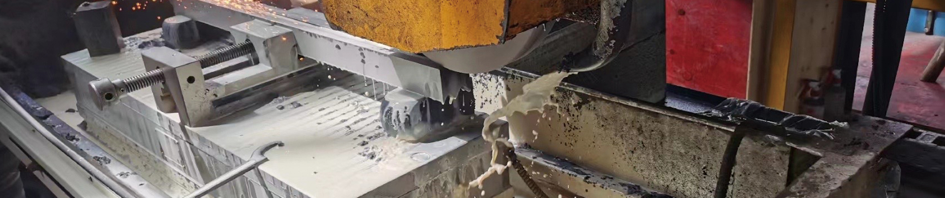

Slitter knife wear is rarely a blade-only problem. When one rotary knife dulls faster than its neighbors, one side of an edge becomes polished, or a replacement blade chips after a few shifts, the cause may be hidden in the interaction between blade geometry, the mating knife, shaft or holder runout, overlap, clearance, side loading, web tension, and the actual material being processed. Buying a harder knife before identifying that interaction can increase tooling costs without correcting the failure.
This practical troubleshooting guide explains how to identify uneven slitter blade wear, distinguish normal dulling from abnormal slitter knife edge wear, measure the machine conditions that drive rotary knife wear, and decide when to correct the setup, regrind a knife, or specify a different material. It covers rotary shear systems used for paper, paperboard, film, labels, foil, and metal coil, while identifying important differences between those machines. It is written for operators, maintenance personnel, production engineers, and industrial knife buyers who need fewer surprises and more accepted output—not just a more expensive blade.
Quick answer: Identify the wear pattern; protect the machine and isolate hazardous energy; measure the knife and its mating surface; verify runout, mounting, clearance, overlap, and loading using the machine maker's definitions; change one variable at a time; and compare knife life in accepted production meters or tons under equivalent conditions. If wear is predominantly abrasive and the process is already stable, then consider alternative steels or a properly selected carbide grade.
For basic knife types and application terminology, see GUANG CHUAN's circular slitter knives selection guide. That guide establishes the equipment vocabulary; the focus here is finding and correcting actual failure mechanisms.
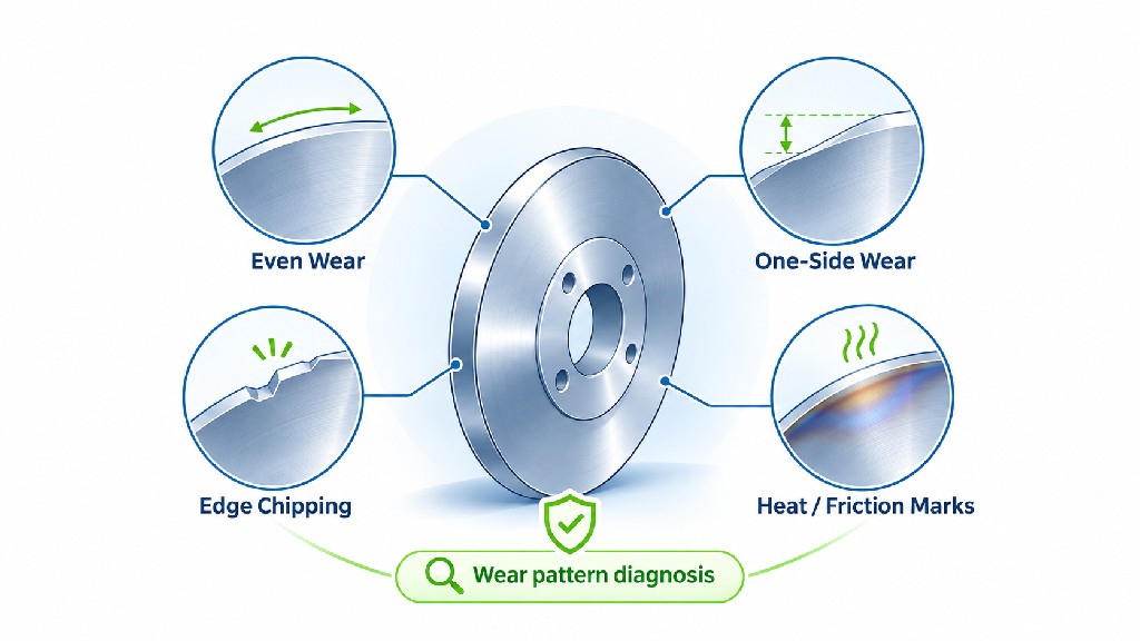
Every cutting edge changes during service. Abrasive particles gradually round the cutting tip, contact with the mating blade produces a narrow polished band, and repeated loading may leave tiny surface marks. Such changes do not automatically indicate defective steel or workmanship. A knife may remain acceptable for thousands of production cycles while its edge gradually becomes less sharp. The maintenance question is whether the tool's condition is predictable and whether the cut still meets the product specification.
Uneven wear means that the rate, location, or type of deterioration is not reasonably consistent with the intended contact pattern and a qualified production baseline. It can appear around the circumference of a single knife, across its two faces, between upper and lower tools, or across several cutting stations on one line. A 360-degree polished track that matches the designed shearing contact is different from one isolated gouge, a repeated notch at the same angular position, or a heavily worn band on only one side face.
The useful first distinction is wear distribution versus wear severity. A lightly but unevenly worn knife may signal a developing problem before output becomes unacceptable. A uniformly rounded edge may be normal end-of-life rather than an alignment issue. A single impact chip in an otherwise new edge points toward an abrupt mechanical event or foreign material, not gradual abrasive deterioration. Operators should describe what they see before trying to assign blame.
Photograph both faces and the full circumference of every suspicious knife. Mark the working side, machine position, direction of rotation, and the observed defect on a simple sketch. The orientation matters: once a blade is removed and placed on a bench, a statement such as "the left side is worn" may no longer identify the contact face that experienced the load.
Industrial slitting stations combine sharp exposed edges with stored pneumatic pressure, springs, rotating arbors, drives, and moving material. A knife that can be inspected safely from behind an approved viewing guard during normal operation must not be touched, measured with a handheld gauge, or adjusted while the machine is moving. Any inspection that requires entry into the cutting zone must follow the site's approved energy-isolation procedure. In the United States, OSHA 29 CFR 1910.147 establishes requirements for control of hazardous energy during covered servicing and maintenance work; applicable local laws and machine-specific instructions must also be followed.
Before taking a failed knife off the line, capture enough information to reproduce the symptom. Note the product grade and thickness, coil or roll identification, line speed, recorded tension, number and width of cuts, holder position, time since installation, total accepted output, and why the line stopped. If one lane has a visible defect, retain representative cut samples from that lane and two neighboring lanes with their orientation identified.
After the authorized shutdown and verified isolation, check for stored energy, disengage or secure holders as specified by the OEM, and use appropriate cut-resistant handling practices. Do not bypass guards to improve visibility. Do not bring loose measuring instruments near rotating knives. If a test requires controlled movement, it should be performed through an approved maintenance procedure by trained personnel with guarding restored or equivalent protective arrangements established.
Safety limit: A chipped, cracked, loose, or visibly distorted high-speed knife should be removed from production and assessed against the machine's rejection criteria. Do not try to "run it smooth" or compensate for a crack by increasing side force. This article offers diagnosis, not permission to override a machine builder's safety or setup limits.
A baseline should distinguish actual tool deterioration from loss of cut quality caused by the process. For example, web flutter or incorrect rewind tension may create fuzzy film edges while a knife remains sharp. Likewise, a coil's tensile-strength or thickness change can increase burr height without an immediately visible change in the edge. Establishing a baseline prevents an unnecessary cycle of buying, installing, and blaming replacement knives.
The table below connects observations to possible mechanisms and first checks. Its entries are diagnostic hypotheses rather than definitive diagnoses. Several causes can coexist, and identical symptoms can occur on different machine types. Record the measurement that supports or rules out each hypothesis.
| Observed condition | Possible causes | First controlled checks | Potential corrective direction |
|---|---|---|---|
| One face deeply polished; opposite face relatively clean | Excessive side contact, wrong orientation, holder cant, axial shift | Compare face contact, holder setting, axial movement, mating ring | Restore intended geometry and approved loading |
| Chips concentrated in one circumferential area | Knife strike, foreign inclusion, runout, damaged mounting face | Index chip position; inspect lower knife, hub, bore and fasteners | Remove impact source; replace unsafe knives |
| Regular intervals of edge or cut defects | Rotating eccentricity, drive oscillation, bearing movement | Measure axial and radial total indicated runout; compare defect pitch | Correct mounting, bearings or shaft assembly |
| Fuzzy paper edges and unusually short blade life | Dulling, excess overlap, high side load, incorrect cant | Check OEM holder recipe and knife condition | Correct engagement; regrind or replace when justified |
| Film tails, stretching or inconsistent edges | Rounded edge, poor support, tension variation, adhesion | Inspect film, web path, blade finish and tension history | Stabilize presentation and select correct edge geometry |
| Metal-coil burr concentrated at one cut | Local clearance error, worn knife, spacer error, shaft deflection | Measure per-cut gap and burr on both edges | Restore stack geometry and edge condition |
| All knife stations deteriorate soon after material change | New abrasive coating, higher-strength stock, process mismatch | Compare certificates, web build, speed and output logs | Qualify recipe; then trial an appropriate knife grade |
| Freshly reground knife fails quickly | Grinding burn, burr, wrong bevel, lost flatness, mismatch in OD | Review regrind record, profile, dimensions, finish | Correct grind specification and paired-tool matching |
Some of these associations are documented in equipment-maker guidance. For example, the Tidland Performance Series Automatic Knifeholder manual lists excess overlap, high side force, and driven-anvil runout as contributors to short blade life in its troubleshooting table. That is valuable evidence about the listed knifeholder family—not an instruction to transplant the same numerical settings into an unrelated machine.
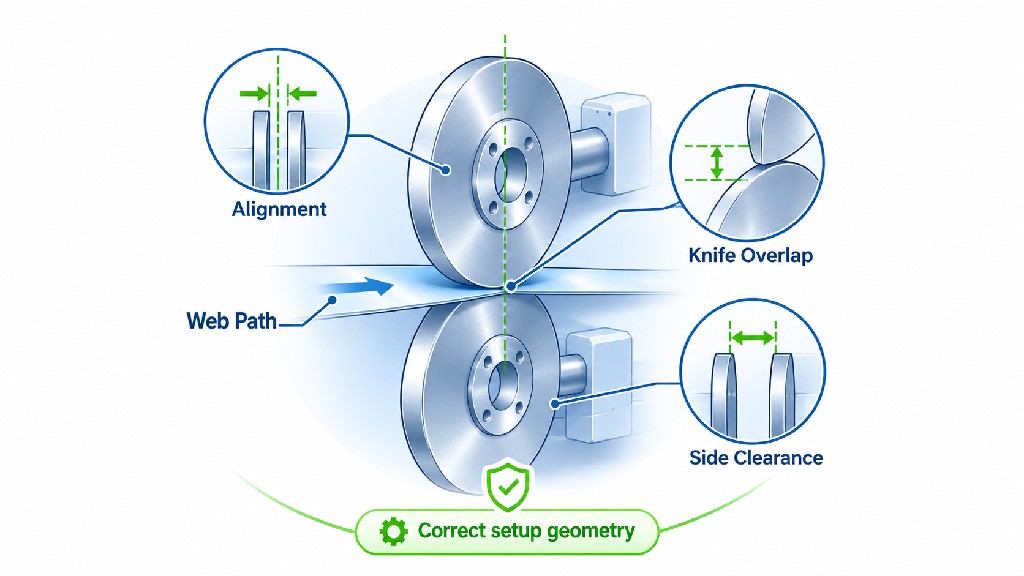
On many rotary shear web slitters, the upper and lower cutting circles must engage in a controlled manner to establish a stable cut point. Overlap describes their relative geometric engagement; side loading is the lateral force maintaining the intended contact between working faces. Excessive overlap can lengthen unwanted rubbing, change the effective cutting point, and contribute to dust, heating, edge deformation, or premature wear. Too little overlap may permit an interrupted slit or unstable knife engagement. Neither failure is fixed by an arbitrary "maximum pressure" setting.
Check the approved reference zero, measurement direction, knife diameters, and whether the holder operates with a wrapped or tangential web path. An adjustment value without those definitions is not transferable. A single-turn knob or pneumatic setpoint may produce different contact conditions after changing the upper knife diameter, worn anvil ring, holder cartridge, or machine geometry.
Start with the qualified recipe for the substrate. Inspect whether the web is presented to the intended cut point and whether the knifeholder reaches and maintains its commanded position. If the cut is unstable, test the minimum permitted change that addresses the symptom, keeping side force, speed, and tension fixed. Recheck quality both immediately and after the line reaches normal operating conditions.
The GUANG CHUAN guide to slitter knife overlap explains the measurement distinctions and why published starting values are system-specific. It also explains why geometric overlap must not be confused with penetration into the workpiece during metal shear fracture.
Suppose a holder has worn guides and the top knife moves slightly away from the anvil at production speed. Increasing overlap may temporarily stop intermittent uncut sections. The machine then appears to improve, but the worn guide remains. The larger engagement adds contact and may accelerate slitter knife edge wear; when the guide deteriorates further, cutting problems return. The correct maintenance decision is to inspect guide play and restore the holder, not to keep advancing the knife indefinitely.
On a metal-coil stack slitter, use the line builder's terminology rather than importing the web-shear definition. Rigid knife stacks typically require controlled lateral clearances and a vertical relationship defined for that machine. Contact-loaded web-shear guidance cannot be assumed suitable for a controlled-gap steel-coil line.
In a contact-loaded upper-knife holder, side force keeps the shearing faces engaged. Excess force may create avoidable face rubbing, heat, and rapid edge dulling; insufficient force can allow separation and poor cut quality. Pneumatic pressure is only an input to a holder mechanism and does not necessarily equal the actual lateral force at the cutting edge. Cylinder area, springs, friction, geometry, and wear all affect the relationship.
A common symptom is a bright band on the working face, often with wear that becomes much more aggressive after someone increases the air-pressure setting. Do not interpret a high pressure gauge reading as proof of correct knife contact. Confirm supply pressure against the holder manual, inspect regulators and lines, and verify that cartridges, springs, guideways, and mounting hardware move freely within their design. If one position requires exceptional pressure to achieve the same cut, investigate that position mechanically.
Holder cant angle or shear angle is the orientation of the upper knife relative to the lower knife. It is not the bevel angle ground on the knife's cutting edge. A wrong cant key, reversed component, or improperly set holder may change contact location and loading, so a sharp new knife can become heavily worn on one face. The guide to slitter knife bevel angles explains the difference between machine cant and cutting-edge geometry.
Inspect the corresponding lower knife or anvil as well. A smooth new upper knife working against a chipped, grooved, eccentric, or poorly aligned lower ring can fail before its material properties matter. Treat upper and lower knives as a functional pair; consult top and bottom slitter knife setup guidance before approving a change of blade profile or orientation.
Where the machine does not use a pressure-loaded contact holder, this procedure does not apply. For stacked coil knives, evaluate spacer geometry, clearances, separator rings, and arbor support instead.
Rotary knife wear becomes highly sensitive to runout because a tiny geometric error repeats every revolution. Axial runout is the sideways variation of a reference face during rotation; radial runout is variation at the outside circumference. Axial movement can modulate side contact and lateral clearance. Radial movement changes engagement and the effective cut point. In practice, shaft deflection, knife eccentricity, worn bearings, dirty mounting faces, uneven clamping, and regrinding errors may contribute to measured movement.
The DIENES Slitting Reference Guide, second edition explains how axial and radial runout can increase cyclic loading, blade dulling and slitting dust. Its published examples for one speed tier include axial total indicated runout of 0.002 inch and radial total indicated runout of 0.004 inch. These are historical guidance figures from a particular source, not universal acceptance limits for all modern slitters.
| Published DIENES reference (one illustrated speed tier) | Inches | Millimeters | Micrometers | Interpretation |
|---|---|---|---|---|
| Axial T.I.R. | 0.002 in | 0.0508 mm | 50.8 µm | Illustrative source reference, not a universal pass/fail limit |
| Radial T.I.R. | 0.004 in | 0.1016 mm | 101.6 µm | Illustrative source reference, not a universal pass/fail limit |
The conversions use 1 inch = 25.4 mm. A demanding thin-web line may require much tighter performance, while a heavy-duty metal stack may define a completely different allowable runout at specific datums. Always use the machine drawing, holder specification, speed regime, and measurement method to determine what is acceptable.
Under verified isolation, mount a calibrated dial indicator on a rigid reference and measure the same feature used in the knife drawing or OEM inspection method. Slowly index the arbor by the permitted maintenance method, record minimum and maximum readings, and calculate total indicated runout as their difference. Record whether the value is measured at the knife face, outside diameter, bare arbor, or assembled lower ring. Different locations tell different stories and should never be mixed in a trend chart.
Repeat the check after removing and cleaning the knife's seating surfaces. A metal chip, adhesive residue or damaged shoulder can create a tilt that disappears when the mounting is corrected. If a suspect knife passes on a verified fixture but fails when installed, the cause is probably not only the blade body. If the runout follows the knife into a different qualified position, examine its bore, concentricity, flatness and grinding history. Do not perform such position swaps if the parts are not approved as interchangeable.
One crucial trap is measuring only the outside diameter of a loose knife on a bench. That tells nothing conclusive about its behavior after clamping, spring deflection, bearing play, and working loads are introduced. For diagnosing intermittent slit defects, the installed condition often matters more than the catalog tolerance alone.
A slitter knife is not defined by outside diameter, bore, and nominal steel grade alone. The edge's included angle, number of bevels, relief, face finish, dish, thickness, and working-face orientation determine where cutting and rubbing take place. Replacing a single-bevel right-hand knife with a visually similar left-hand tool can move the contact face to the wrong side. A grinding shop that changes a hollow-ground profile into a flat bevel can increase the contact area even if the new knife is nominally sharp.
When one-sided knife edge wear appears after a purchase or regrind, compare the replacement with an approved unused sample. Ask whether both knives were measured from the same datum, whether the bevel was mirrored, and whether there is a raised burr at the very edge. Observe the actual contact track before concluding that the steel is too soft. A mechanically correct, modestly hard edge can outperform a much harder knife with the wrong cross-section.
Terms on drawings must remain precise. The bevel angle belongs to the knife cross-section; the cant angle belongs to its installed orientation; overlap describes cutting-circle engagement in the specified machine; clearance has different definitions in web converting and metal slitting. Unclear drawings create expensive repeat-order mistakes because the purchaser and manufacturer may each be measuring a different feature.
Surface finish is also functional. Rough ground faces can increase contact friction and trap adhesive or coating residues. Overpolishing or changing an edge microgeometry without qualification can be harmful too, particularly if the edge needs a specific land or microbevel for toughness. Define the required face finish and edge condition based on approved performance rather than requesting the smallest possible roughness number regardless of application.
Drawing checkpoint: Every custom knife order should identify OD, ID, thickness, flatness, concentricity/runout datum, profile cross-section, working-face direction, material/heat treatment, expected regrind allowance, and whether the knife is supplied singly or as part of a matched set.
Not all visible tool deterioration is the same wear mechanism. Abrasive wear occurs when hard particles, mineral fillers, metal oxides, fibers, or other constituents progressively remove or deform a cutting surface. Adhesive wear or material transfer involves local sticking and subsequent tearing, smearing or pickup. Fatigue-related damage can arise from repeated loading; impact or unstable contact can cause sudden edge chips. Heat, corrosion, and improper cleaning can add further damage. These mechanisms sometimes overlap on one knife.
Look for a consistently worn band and progressive loss of edge sharpness over an otherwise stable run. Paper coatings, abrasive fillers, some composite films, and surface oxides can contribute to abrasion. If the knife shows gradual and repeatable dulling after the holder and counterpart tool are verified, material selection becomes commercially relevant. A qualified HSS or carbide alternative may hold its geometry longer, but the benefit must be measured against its price, resharpening difficulty, and susceptibility to chipping.
Adhesive tapes, pressure-sensitive labels, certain polymer films, and soft metals can deposit material on a working face. A buildup band changes effective geometry and may increase friction, stretching or edge roughness. It can also make a cutting defect look like slitter blade failure. Follow the machine and blade maker's approved cleaning method, record how quickly deposits return, and inspect the underlying edge after cleaning. Aggressive scraping or unapproved solvents can damage coatings, brazed joints or finishes and introduce their own failure mode.
Edge chipping is not ordinary dulling. It can follow a knife collision during engagement or retraction, intermittent contact from runout, a hard inclusion, poor support, or inappropriate material toughness. The DIENES reference guide describes damage associated with wrongly timed upper-knife movements; its message is to check engagement sequencing, not simply to increase the blade hardness. A hard, wear-resistant material may lose larger chips when the system is impact-prone.
Excess rubbing can raise local temperature and accelerate loss of edge quality. Regrinding with poor coolant delivery or excessive stock removal can create thermal damage or distortion before the knife is even installed. Corrosion marks from wet processing, unsuitable storage, or aggressive cleaners can form stress-concentrating pits. Distinguish these appearances from direct mechanical abrasion and document whether the damage originated in production, maintenance, transport, or storage.
Where failure mechanism is uncertain, preserve a cleaned but otherwise unmodified specimen for magnified examination and, if justified, metallographic investigation. Regrinding every suspect edge immediately destroys evidence that could identify the original cause.
Searches for "slitter knife wear" often return advice as if one machine geometry applies to every substrate. That is misleading. Paper and film converters often use individual upper knives against driven anvils with pneumatic or mechanical holders. Some web lines use razor blades or score knives instead of rotary shear pairs. Metal coil slitters frequently use rigid upper and lower arbors with alternating knives, spacers, and separator or stripper rings. Their working loads, clearance conventions, failure signatures, and acceptable edges differ substantially.
| Material / process | Frequently observed symptoms | Wear or process factors to investigate | Practical priority |
|---|---|---|---|
| Uncoated paper and tissue, rotary shear | Fiber pull, fuzzy edges, dust | Edge rounding, overlap, incorrect cant, web stability | Examine edge and holder setup together |
| Coated paper and paperboard | Dust, coating debris, rapidly dulling edge | Mineral abrasion, contact area, support, debris handling | Validate stable geometry before grade upgrade |
| BOPP, PET, PE and laminates | Film tails, necking, stretched or heat-affected edges | Edge profile, adhesion, web tension, nip or anvil behavior | Separate tension faults from knife deterioration |
| Adhesive labels and tape | Pickup, sticking, rough or contaminated edges | Adhesive transfer, face finish, cleaning interval | Quantify residue and cleaning-related downtime |
| Thin metal foil | Micro-burr, particles, edge waves | Runout, fine geometry, support, possible contact damage | Use magnified edge acceptance checks |
| Carbon or stainless steel coil | Burr growth, rollover, unequal fracture, chipping | Per-cut clearance, strip strength, arbor support, knife toughness | Measure the cut edge and complete knife stack |
For paper specifically, see how to reduce paper dust, fraying, and rough edges. For film constructions, consult film slitting blade selection for BOPP, PET, PE, and laminates. These applications should not share a universal service-life claim because even a change in coating or adhesive formulation can alter how a knife behaves.
Imagine a converter using the same knife dimensions for two different coated paper products. The first product produces an acceptably clean edge over a long run; the second shows growing dust after a short interval. Possible explanations include a higher abrasive filler content, different caliper, increased tension, changed slit width, altered web presentation, or a subtle holder adjustment made during the grade change. A laboratory hardness certificate on the blade does not distinguish among these causes. A controlled side-by-side trial does.
For a metal service center, the analogous problem might occur when a knife stack qualified for annealed stock is used on higher-strength material of the same nominal thickness. The contact load and fracture behavior can change. A knife that chips is not necessarily a counterfeit grade; it may be experiencing an unqualified loading condition. Check the material certificate and the line builder's guidance before approving another blade purchase.
In a controlled-gap metal-coil slitter, the horizontal clearance at one shear plane generally means the lateral spacing between the working upper and lower knife faces. It affects the progression of deformation and fracture, the proportion of burnished and fractured surfaces, and the size and shape of burrs. However, some machine drawings use a combined two-edge allowance, while others specify a per-cut value. A numerical percentage is meaningless until the measurement convention is confirmed.
For a defined clearance C at one cut and strip thickness t, the arithmetic percentage is 100 × C / t. Conversely, C = t × p / 100 when p is the chosen percentage. These expressions are dimensional bookkeeping, not a universal recommendation of what percentage a specific steel needs. The mechanical suitability of a trial depends on grade, temper, thickness, strength, edge acceptance, and machine design.
| Hypothetical strip thickness | Illustrative percentage only | Computed per-cut clearance | What the example proves |
|---|---|---|---|
| 0.50 mm | 5% | 0.025 mm (25 µm) | Small setup changes become significant on thin strip |
| 0.50 mm | 8% | 0.040 mm (40 µm) | A percent must be translated into a measured gap |
| 0.50 mm | 12% | 0.060 mm (60 µm) | Different trial values materially change the gap |
Important: 5%, 8%, and 12% above are deliberately chosen arithmetic examples. They are not approved clearance settings for aluminum, carbon steel, stainless steel, or any named grade. The machine maker's method and trial evidence govern the setting. See the detailed metal coil knife selection guide and the accompanying metal-coil burr troubleshooting guide for additional context.
After a permitted setup adjustment, inspect both sides of the slit strip. A typical sheared metal edge contains rollover, a smoother burnished zone, a fractured zone, and a burr. Compare those features at several lane positions and along the coil, then correlate measurements with actual tool geometry. If the fracture and burr patterns are asymmetric, investigate the knife stack, spacers, arbor deflection, strip crown, and separator rings. An aggressive change in clearance can introduce a new problem even if it temporarily reduces burr in one sample.
Do not carry a thin-web shear holder's side-force specification into a rigid metal knife stack. Conversely, do not use a steel-coil clearance chart to set the lateral relationship of a contact-loaded paper slitter. Both are called rotary shear systems, but they do not necessarily use the same definition of the cutting gap.
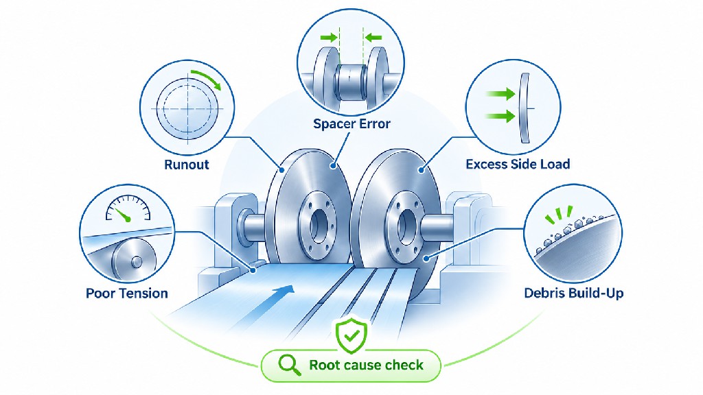
Blade life is often limited by the parts holding the blade in place. A perfectly ground knife can run eccentrically on a worn shaft; a concentric knife can tilt on a dirty shoulder; a sharp cutting pair can rub unevenly when a pneumatic holder loses its lateral guidance. Rather than inspecting only the failed blade, examine the chain of components that positions and loads it.
Check locating shoulders, shaft straightness, approved bearing play, keyways, clamping threads, and contact surfaces. Where multiple knives share an arbor, small errors can accumulate across the stack. Record measured installed runout under consistent conditions. A shaft that passes unloaded inspection but deflects under production load may require a broader machine engineering review rather than repeated knife replacement.
Spacers control the position of stacked knives and can be as important as the blades themselves. Inspect for thickness variation, damage, embedded debris, burrs, and mixed sets that were not manufactured to the same functional tolerance. A ground knife placed against a damaged spacer may tilt or move, creating localized clearance variation. Mark and preserve a stack diagram before disassembly so the original sequence can be reconstructed accurately.
Check for loose guide-bar clamps, worn gibs, play in the moving cartridge, sticky pneumatic actuators, damaged seals, and incorrect retraction behavior. Some holders sequence vertical movement and side engagement specifically to avoid blade collisions. If a new holder or an upgraded cartridge changes that sequence, validate its setup procedure rather than assuming the old recipe remains correct. The Tidland maintenance and troubleshooting manual explicitly points users toward loose holders, cant components, runout and overlap when investigating slit-quality problems.
A heavily used lower anvil may develop grooves, chips, or eccentric wear that destabilizes a fresh top knife. Inspect the lower component with the same seriousness given to the upper edge. If the lower knife is approved for alternate working edges or reversal, use only the manufacturer's instructions; reversing a component without confirming bevel and orientation may turn a manageable wear problem into an immediate collision risk.
The most telling observation is whether a problem follows the tool, the holder position, or the material lane. With OEM-approved interchangeable parts and safe maintenance practice, a controlled comparison can help distinguish these categories. A defect that stays with one holder suggests holder geometry; one that follows a knife suggests tool condition; one that appears only with a material or product combination suggests process interaction. The result is not proof by itself, but it narrows the investigation.
When a knife is removed, establish a short inspection routine before cleaning, measuring, or sharpening it. Treat the blade as both a service component and a source of evidence. Label the knife ID, material grade, machine position, working face, orientation, installation date, and cumulative accepted production. If the tool has been reground, include its regrind count and last approved dimensions.
Optical magnification can reveal edge chips and damage patterns that are invisible to the naked eye. However, a photograph taken at unknown magnification, lighting and viewing angle does not provide a reliable numeric edge radius. If the business decision depends on a measured wear land or edge radius, use a defined optical or profilometric method with a consistent fixture and report its measurement uncertainty.
| Inspection record field | Example of a useful entry | Why it matters |
|---|---|---|
| Knife identification | Part drawing revision, serial or lot, station number | Separates part variation from holder-location faults |
| Material and task | Substrate grade, thickness, coating and roll/coil lot | Defines actual cutting duty |
| Accumulated service | Accepted meters or tons since install, not just calendar days | Enables a comparable knife-life metric |
| Operating condition | Line speed, tension, pressure recipe, approved gap and overlap | Identifies process changes and possible confounding variables |
| Failure evidence | Photos, chip locations, worn-face identification, cut samples | Supports a root-cause hypothesis |
| Measured condition | OD, thickness, face/runout readings and edge measurements | Informs resharpen-versus-replace decision |
| Action and outcome | Holder serviced; trial repeated; accepted output improved | Closes the loop instead of repeating the same failure |
These records also make discussions with a knife manufacturer much more productive. "Our blades wear too quickly" is difficult to assess. "Three upper knives on holder 6 showed axial face scoring within 80,000 accepted meters after an anvil change; neighboring holders achieved 220,000 meters under the same product" identifies a testable problem. The numbers in this illustrative statement are not GUANG CHUAN field-test results.
Uniform dulling does not necessarily require a new knife. Many tool-steel and high-speed-steel rotary slitter knives can be precision reground, provided their bodies remain safe and dimensionally suitable. Grinding should restore the specified bevel, working face, edge condition, concentricity and finish while removing only the necessary material. Matched upper and lower configurations may require diameter matching or a coordinated grind schedule to preserve holder geometry.
Resharpening is reasonable when wear is primarily at the edge, chipping is shallow enough to remove within allowance, the mounting bore is sound, and no crack or permanent distortion is present. Replacement is often the safer or more economic choice for cracked blades, severely distorted bodies, badly damaged bores, deep fractures, severe heat damage, or knives worn beyond the machine's allowed diameter range. Consult the GUANG CHUAN resharpening and replacement guide for a more detailed decision framework.
Some problems require a design change rather than maintenance. If a knife consistently develops a wide rubbing band despite verified holder geometry, its profile may be wrong for the intended contact. If an edge chips under unavoidable but qualified impact loading, a tougher steel or altered edge microgeometry may be more suitable. If a stable cutting system shows predictable abrasive rounding that limits run length, a more wear-resistant material can be justified. In each case, define the actual failure mechanism and required finished edge before changing the knife specification.
An incorrect grinding datum can make a knife appear concentric on the grinder but unsuitable in the installed holder. Excessive stock removal can change OD, thickness, or dish; an incorrect bevel may reverse the working-face geometry; poor control of heat can damage the edge; an unremoved burr can create immediate cutting problems. An edge that looks mirror-bright is not automatically geometrically correct. Require the grinding provider to preserve the specified profile and record final critical dimensions.
Track the economics of each regrind instead of assuming sharpening is always cheaper. Include transportation, inspection, grinding cost, any paired-set work, remaining usable life and the time before the next changeover. A knife with only a small amount of stock remaining may be technically sharpenable but commercially inferior to a replacement. Conversely, a stable tool that can complete several qualified regrinds may have a favorable cost per accepted meter despite a higher purchase price.
Knife material selection matters after the process has been stabilized. D2-type cold-work tool steel provides wear resistance and a common cost baseline in many industrial knife applications. M2 high-speed steel is a candidate where a balance of edge performance, thermal resistance and wear resistance is desirable. Cobalt-bearing M42 can be attractive in selected demanding conditions. Cemented tungsten carbide can offer substantial abrasion resistance in suitable stable cutting systems, but grade, binder content and mechanical damage tolerance are central to its success.
Higher nominal hardness does not guarantee longer slitter knife life. A very hard edge working against an eccentric anvil or striking a misaligned mating knife may chip sooner than a tougher conventional tool. Carbide is a family of engineered materials rather than one guaranteed performance grade. Similarly, heat treatment and finished edge geometry can make two knives labeled "D2" behave differently. Specify actual grade identity and acceptance requirements, not a marketing superlative.
| Material family | Commercial reason to test it | Failure risk to check | Best trial evidence |
|---|---|---|---|
| D2-type cold-work steel | Competitive baseline for many general-purpose cutting duties | Premature wear in highly abrasive service; cracking under unsuitable loading | Qualified life, edge quality and regrind allowance |
| M2 high-speed steel | Potential step up when conventional steel dulls before planned stops | Cost increase without actual life benefit | Matched A/B run with comparable geometry |
| M42 cobalt high-speed steel | Candidate for specific demanding wear and thermal conditions | Hardness premium with no performance gain or greater damage sensitivity | Measured service life and chip frequency versus M2 |
| Cemented tungsten carbide | Candidate for abrasive, high-volume precision slitting with stable contact | Chipping, fracture, handling and specialized regrind costs | Accepted production per tool plus breakage and changeover records |
For a fuller comparison of representative hardness values, chemistry, toughness trade-offs, and pricing logic, consult D2 vs M2/M42 HSS vs tungsten carbide slitter knives. The material recommendation for a purchase order should follow the specific machine load, substrate, cutting method and trial acceptance. Steel hardness reported in HRC and carbide hardness reported in HV or HRA are different scales and cannot be ranked by comparing their raw numbers.
A useful buying strategy is to retain the proven blade as the control and qualify one alternative at a time. Keep geometry, mounting and the product mix as equivalent as possible. If a supplier proposes both a material upgrade and a different bevel, run the experiment in stages if practical; otherwise the buyer will not know which change created the outcome. Where a production interruption is very expensive, a small qualification lot with a pre-agreed inspection and reporting plan is usually more defensible than a large speculative purchase.
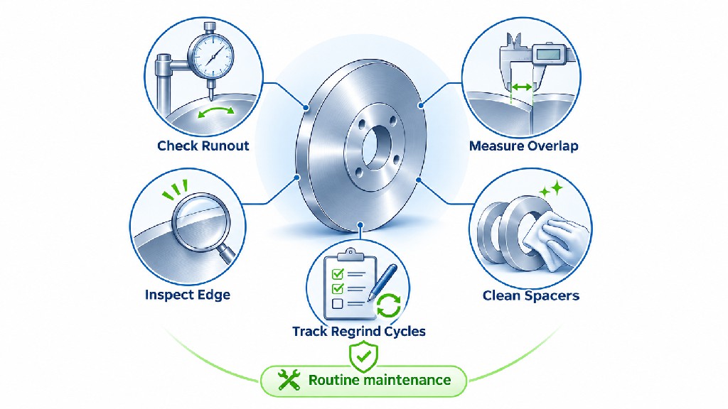
Teams often lose time because several adjustments are made simultaneously. A standard sequence gives operators a clear escalation route and creates usable maintenance evidence. The following procedure is an operational framework to adapt to approved machine and safety requirements, not a replacement for the OEM manual.
Is the line failing because burr height exceeded a customer limit, because paper dust became excessive, because film tails appeared, or because a knife physically chipped? Set a measurable defect or inspection rule before diagnosing the blade. Where possible, save both acceptable and unacceptable samples from the same product.
Map the defect by lane, knife number, roll length, coil position and elapsed accepted output. A defect appearing in every lane at the same moment suggests a system-level change. One persistent lane can point to its holder or mating knife. A repeating defect pitch may suggest rotating eccentricity, though this must be confirmed by machine measurements.
Follow energy isolation and guarding requirements. Record knife damage, residues and installation orientation before disassembly. Remove visibly unsafe components from service. Never use an improvised hand-contact test to feel knife sharpness or side pressure.
Verify knife location, mating face, bore fit, clamping shoulders, spacers, lower ring condition, guide-bar security, and any allowable axial or radial runout. Compare with machine-specific tolerance documents. An incorrect installation can make identical knives behave differently.
Confirm the correct definitions and settings for overlap, lateral clearance, cant, pressure, web tension, line speed and the actual substrate. Do not use values copied from an unrelated line. Correct one discrepancy at a time and note the action.
Repeat the same product under a comparable speed and operating condition. Inspect samples at defined intervals rather than judging the first few meters. Record actual accepted output, defect severity, blade damage and any new abnormal noise or vibration. Stop the trial if a safety concern appears.
Record which measured fault was corrected and whether the result repeated on a later production run. If the issue was caused by holder wear, add that check to preventive maintenance. If the issue was confirmed abrasive wear on a stable system, make the supplier's material qualification part of purchasing. If no clear cause was found, identify the next measurement instead of declaring the problem solved.
Decision rule: A replacement knife is not a successful corrective action merely because the slit looks good immediately after installation. The evidence should show that accepted quality is maintained over the planned production interval without an abnormal wear pattern returning.
An effective preventive-maintenance program does more than schedule knife changes. It monitors the conditions that make knife performance repeatable: mounting cleanliness, bearing and holder condition, contact geometry, qualified process settings, edge inspection, and traceable production history. The interval for each task should be set from the machine OEM requirements, wear trend and local risk assessment. A calendar-only schedule is often weak when the same line processes very different substrates.
| Recommended checkpoint | Suggested event for inspection | Evidence to retain | Reason |
|---|---|---|---|
| Knife faces, chips and deposits | At approved setup/changeover and after abnormal cuts | Visual record and condition code | Find damage before it reaches the product |
| Mounting faces, bores and spacers | During each qualified knife installation | Cleanliness and dimensional inspection results | Reduce avoidable misalignment |
| Holder clamps, guides and pneumatic system | At OEM-prescribed maintenance intervals | Service checklist and corrective work order | Preserve stable engagement and side loading |
| Installed axial/radial runout | After impact, bearing work, regrind or recurring periodic defects | Indicator readings, datum and location | Connect eccentricity to wear and slit defects |
| Cut quality and defects | At setup approval and in-process control intervals | Samples, burr/dust/edge metrics | Change tools based on quality limits |
| Accepted output per knife | At every change or regrind | Meters, tons or validated job units | Estimate true knife life and variability |
This table describes checkpoints, not universal frequencies. A continuously operating high-speed paper mill and a low-volume metal service center will need different schedules. If the machine maker requires daily checks or a specified pneumatic service interval, that requirement takes precedence. Conversely, do not use the word "daily" as a substitute for tracking how much material actually passed through the edge.
Consider setting an internal early-warning threshold based on each line's own baseline rather than an invented industry limit. For example, a team may review knives whose accepted output falls materially below the median for equivalent jobs, or stations with recurring one-sided wear. Use enough comparable runs to understand normal variation. A short pilot series does not justify calling the result a universal mean time between failures.
Statements such as "this knife lasts three months" are too vague for meaningful purchasing comparisons. A knife cutting a few hours each week can remain installed longer than a knife operating continuously, even if the latter has better wear resistance. Likewise, a long-running blade that generates unacceptable dust or burrs for its final shift has not necessarily delivered more useful production than a shorter-lived tool.
A practical metric is accepted production length between qualified knife interventions, reported as meters, feet, tons or good rolls per knife or matched knife set as appropriate. Define precisely what counts as an intervention: new knife replacement, first resharpening, unplanned cleaning, knife reversal or adjustment. Keep quality standards equivalent. The metric can then be paired with direct tool cost, changeover time and rejection rate.
Knife life (accepted meters) = accepted output after installation and before the defined end-of-life event. For a series of comparable runs, record every actual observation rather than quoting only the best run. If some knives have not yet reached end of life, label them as ongoing/censored observations rather than treating their current output as a final failure life. A simple spreadsheet with install and removal dates, accepted meter readings, substrate, failure mode, and tool lot is already a major improvement over a verbal impression.
Where possible, compare two tool specifications on the same machine, with the same material grade or documented job mix, similar speed and a fixed edge acceptance criterion. If product demand requires a mixed campaign, stratify the results by substrate family. A knife used mainly for uncoated paper should not be compared directly with one cutting a mineral-filled coated stock and presented as a fair material test.
Repeatability matters as much as maximum life. An alternative knife that occasionally lasts an extraordinary long time but also chips unpredictably may be a worse business choice than a slightly shorter-lived tool with stable, planned service. Track the distribution of outcomes and reason for removal, not only average accepted meters. This is especially important on production lines where an unplanned stop disrupts several downstream processes.
Buying decisions become clearer when the unit price of a knife is separated from the cost of keeping the line producing acceptable material. Consider a hypothetical comparison of two approved matched knife sets on the same line. Set A costs less to purchase but needs intervention more often. Set B has a higher purchase price and achieves a longer interval between qualified changes. The values below are invented for calculation training; they are not GUANG CHUAN quotations, industry averages, or measured case-study outcomes.
| Illustrative assumption or calculated result | Set A: baseline steel | Set B: qualified alternative |
|---|---|---|
| Purchase price per matched set | US$360 | US$470 |
| Accepted meters per change interval | 150,000 m | 240,000 m |
| Expected set intervals per 1,000,000 accepted meters | 6.67 | 4.17 |
| Changeover duration per event | 0.75 h | 0.75 h |
| Assumed downtime cost per hour | US$240 | US$240 |
| Modeled tooling spend per 1,000,000 accepted meters | US$2,400.00 | US$1,958.33 |
| Modeled downtime cost per 1,000,000 accepted meters | US$1,200.00 | US$750.00 |
| Total modeled listed cost | US$3,600.00 | US$2,708.33 |
| Listed cost per 1,000 accepted meters | US$3.600 | US$2.708 |
For a long-run planning model, set intervals per million accepted meters = 1,000,000 divided by accepted meters per set. The modeled total then equals expected intervals multiplied by (price per set + changeover hours × downtime cost per hour). Under these assumptions, Set B reduces the two listed cost categories by about 24.8%, even though its upfront price is higher. The calculation uses fractional expected intervals as a planning convention; actual purchases and changes take place in whole sets.
This simple comparison deliberately excludes taxes, freight, stock holding, blade regrinding, cleaning labor, scrap, returns, quality claims, and the consequences of unexpected breakage. Add those categories if they are material to your decision. If the two sets do not meet the same acceptance criteria, the calculation is not an apples-to-apples comparison. A knife that runs farther but produces unacceptable edges is not automatically the better commercial solution.
The inverse conclusion is just as important. If Set A already survives a planned campaign with stable quality, Set B's longer theoretical wear life may not save any changeover time. An expensive upgrade is justified only when it addresses an actual constraint: abrasion, unpredictable stoppages, quality drift, or a planned maintenance interval that the baseline tool cannot meet.
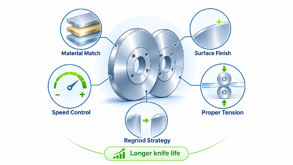
The following examples are illustrative diagnostic scenarios, not documented GUANG CHUAN customer projects. Their purpose is to show how a plant can move from symptom to evidence and action without presuming that a knife material is responsible.
A converter reports that one station develops severe face polishing and dust while the rest of the line remains acceptable. The first hypothesis is inferior blade material. Instead of replacing all knives, the maintenance team records the position, checks the correct working-face orientation, measures installed runout and inspects guide-bar mounting. The suspect station has looseness outside its approved holder specification. After the holder is repaired and an approved knife pair is installed, the team repeats the same product campaign and monitors accepted meters and edge quality. If the wear returns, the next review examines the lower anvil and engagement sequence. A grade upgrade is postponed until the process is stable.
A service center changes from an established carbon-steel product to a stronger stainless strip. Burrs rise on certain lanes and operators ask for harder knives. Engineering first confirms the strip's actual certificate properties and thickness, then reviews the OEM's per-cut clearance definition, spacer plan, separator rings and edge condition. The team measures the cut surfaces and updates only qualified setup variables. It then evaluates whether the knife edge still loses quality faster than the required campaign interval. A new material grade is considered only after the geometry and substrate effect have been separated.
A film converter observes progressive edge tails and a sticky deposit on the cutting faces. A fresh knife appears to help, but the same issue reappears. Inspection finds transfer rather than pronounced metal loss. The team documents the residue, cleans with an approved method, checks tension and support, and tests whether a suitable face finish or alternative process geometry changes the rate of pickup. The business metric becomes accepted meters between approved cleaning stops—not only how long the steel takes to become blunt. Purchasing avoids an unsupported promise that a harder carbide tool will eliminate adhesive transfer.
All three scenarios lead to a useful supplier conversation, but the requested solution differs: restore holder precision, qualify coil setup, or reduce adhesive pickup. "Better knife" has no technical meaning until the required improvement is identified.
A precise request for quotation makes it easier to compare suppliers and prevents the same mistake from being repeated in a new blade. GUANG CHUAN's company information describes made-to-drawing and sample-based industrial cutting-tool production. For a problem involving premature rotary knife wear, the most useful inquiry is a combination of the knife specification and the documented cutting duty.
| Information to provide | Minimum useful detail | Question it helps answer |
|---|---|---|
| Machine and process | OEM, model, shear/razor/score method, holder or arbor arrangement | Is this the correct knife family? |
| Blade geometry | Drawing/revision, OD, ID, thickness, bevel, dish, mating faces, runout datums | Will the replacement fit and cut correctly? |
| Material and treatment | Known grade, finished hardness specification, heat-treatment or coating information | Is a change in material justified? |
| Substrate duty | Paper coating, film construction, foil alloy or metal grade, thickness and strength | What loading and wear mechanism should be expected? |
| Operating recipe | Line speed, overlap/clearance definitions, pressure or tension, number of cuts | Could the setup be driving abnormal contact? |
| Evidence of failure | Images of both knife faces, failed cut samples, defect location and pattern | Is the failure abrasion, pickup, rubbing or impact? |
| Life and economics | Accepted output per set, changes, regrinds, downtime and annual volume | What improvement would be commercially valuable? |
| Acceptance criteria | Maximum burr, dust, particle, edge appearance and dimensional limits | How will a proposed solution be qualified? |
When sending a physical sample, clearly label whether it is unused, worn, chipped or reground. A worn blade's current OD must not automatically be treated as its original manufacturing diameter. State if a drawing should control over the sample. If there is no drawing, provide the machine model and any original tooling documentation so a new part is not reverse-engineered from wear damage alone.
Ask suppliers to distinguish a like-for-like replacement from a proposed engineering change. A changed bevel, harder grade, different carbide composition or modified thickness should be identified and qualified separately. For repeat procurement, request a controlled drawing revision, material identity, critical dimension report, finished edge inspection and lot traceability appropriate to the tool's risk and cost.
The likely cause may be local to that position: loose holder mounting, incorrect cant, runout, a damaged lower ring, poor spacer contact or a different loading condition. Compare the suspect station with adjacent qualified stations using the same substrate and record whether the problem follows an approved interchangeable tool, stays with a holder, or tracks a material lane. Knife steel quality should be assessed after these differences are checked.
Eccentric mounting, radial runout, axial movement, intermittent contact and localized impact can create nonuniform circumferential patterns. A rotating defect may also appear as a repeating mark on the slit product. Measure installed runout at a defined datum, inspect clamping surfaces and bearings, and compare the defect location with the knife's indexed angular position.
Yes, in applicable rotary shear web systems, excessive engagement can increase rubbing and wear. Equipment-maker documentation identifies excess overlap among possible causes of short blade life. Too little stable engagement can also impair cutting. The correct value depends on the knifeholder and process, so use the OEM's approved definitions and settings rather than a universal overlap number.
No. Insufficient force can destabilize contact, while excessive force can accelerate face wear. The correct range and adjustment method are specific to the knifeholder. Pneumatic pressure is not automatically equal to the actual cutting-edge contact force. Check the complete holder and mating knife before increasing a regulator setpoint.
No. Predictable dulling on a structurally sound knife may justify qualified resharpening. Sudden chips, cracks, damaged bores, distortion or excessive material loss may require replacement. Verify geometry and machine limits before deciding. An apparently dull knife may also be affected by adhesive buildup or a process condition rather than loss of cutting metal.
No material is universally longest-lived. D2 can be an economical baseline; M2 and M42 are candidates for more demanding wear conditions; suitably engineered cemented carbide can be effective against abrasion but is sensitive to its grade and damage environment. The practical winner is the qualified tool that produces the most acceptable output at the lowest relevant total cost.
Compare the new tool against the approved drawing and a known-good sample: OD, bore, thickness, working-face orientation, profile, finish, runout, and material or hardness evidence. Record installation and holder measurements as well. A part can meet its drawing and still fail because of a damaged mating knife or unsuitable process; a part can also be sharp but dimensionally nonconforming.
Possible explanations include an incorrect bevel orientation, an edge burr left after grinding, too much overlap, wrong cant angle, unstable holder, improper web presentation or a damaged lower knife. Immediate fuzziness is not sufficient evidence of poor blade metallurgy. Compare the installation with a proven recipe and inspect cut samples before buying an alternative material.
Track accepted meters or tons between defined interventions, together with the reason for removal and relevant edge-quality criteria. Add unplanned downtime, scrap, regrind count and blade cost per accepted output unit. Separate data by substrate and machine when operating conditions materially differ. A stable median and narrow variation may be more commercially valuable than one record-long run.
A credible supplier should not promise zero dust or burrs under all conditions. Cut quality depends on the complete system, including materials, geometry, runout, tension, mating tools and the customer's measurement method. Require a defined trial and an agreed acceptance threshold. Any performance guarantee should identify the relevant substrate, machine setup, operating window and inspection method.
Uneven circular slitter knife wear is a process signal. A heavily polished face may reveal excess contact; a chipped sector may indicate a collision or runout; a line-wide deterioration after a material change may identify an abrasive or higher-load substrate; and rapid edge defects after regrinding may expose profile or mounting errors. The response should follow the evidence instead of a reflexive search for the hardest available steel.
Use three questions to guide action. First, what exactly failed? Define the wear pattern and the accepted-edge criterion. Second, where is the source of abnormal loading? Inspect the machine, mating knife and process variables with a consistent measurement method. Third, what improvement is worth buying? Only after the baseline is stable should a purchaser compare a new material, geometry, sharpening strategy or matched knife set based on accepted output and total cost.
GUANG CHUAN supplies industrial cutting knives and custom tooling for a range of manufacturing processes, including rotary slitting applications. If you are investigating slitter blade failure, send the existing knife drawing or physical sample, substrate details, relevant machine information, photos of the wear pattern, and the accepted output achieved so far. This helps the technical team discuss whether the best next step is a like-for-like replacement, a geometry review, a material comparison, or a controlled trial.
Request a practical slitter knife review. Share your blade dimensions, top/bottom knife configuration, cutting material, observed wear or defect, and target production interval through the GUANG CHUAN contact page. For examples of available slitting-tool designs, you can also view the multi-groove bottom slitter rotary knife. A useful quotation should specify the tool and the performance question that a trial is intended to answer—not promise universal lifetime multipliers.
Technical disclosure: This article combines publicly available equipment-maker guidance, GUANG CHUAN product/application information, and general engineering diagnostic reasoning. The DIENES runout figures are explicitly identified historical reference examples; the metal-clearance numbers are arithmetic examples only; all scenario and financial figures are hypothetical. No statement here should be interpreted as a certified test result, universal knife-life benchmark or substitute for a specific machine OEM's safe operating instructions.

Оставить сообщение
Отсканируйте в WhatsApp :

 Pусский